Overview
For a power-tower lifting frame, the rope hoist is replaced by an integrated lead-screw drive. Motor sizing, the lifting platform and the primary members are designed, modelled in SolidWorks, and checked in ANSYS. Under the present load case the platform von Mises peak is 112.4 MPa and the peak resultant displacement is 0.48 mm; the frame von Mises peak is 19.3 MPa.
Problem
A power-tower lifting frame raises tower sections during erection. The original scheme used wire rope as the lifting element. The load path was long and flexible, the assembly carried extra fittings, and rope stretch, synchronization and eccentric load all affected the platform pose. Making the frame more compact and lighter therefore starts from the mechanism, not from shaving plate thickness on the rope layout.
The redesign has to satisfy three conditions at once:
- the lifting load must travel a shorter, better-defined path into the structure;
- the motor, screw and platform must pack tightly, so members kept only to route the rope can be removed;
- stresses and displacements in the critical sections must remain within the strength and stiffness limits.
The object of this work is the lifting mechanism of the frame, not the tower itself. The deliverables are the kinematic scheme, the platform design and the finite-element check.
Method
The sequence is mechanism, then structure, then verification: fix the lead-screw load path, size the motor and platform to steel-selection practice, and use finite-element analysis on the load-bearing parts.
1. From rope hoist to lead-screw drive
In the rope scheme, force travels through a winch, guides and pick-up points; the path is long and weakly constrained. The lead-screw scheme places drive, transmission and platform on a common axis. Lift force goes from the screw pair into the platform, then into the frame columns.
That change:
- shortens the load path and reduces pose uncertainty from rope elasticity;
- removes sheaves and rope hardware, freeing mass that is not on the load path;
- aligns the main load with the axes of the structural members, which simplifies later section design.
2. Motor sizing and platform design
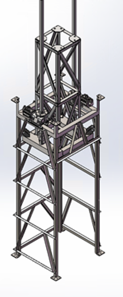
After the lift load, stroke and duty cycle are set, materials follow engineering steel-selection practice and the motor is sized to that load. The platform must carry the lift, the screw-support reactions and the connections to the columns, so the sections are laid out around those three paths rather than drawn first and stiffened later.
The assembly is modelled in SolidWorks to check fit, motion clearance and the geometry handed to finite-element analysis. Mass is removed only off the load path; load-bearing sections are not thinned by rule of thumb.
3. ANSYS strength and stiffness check
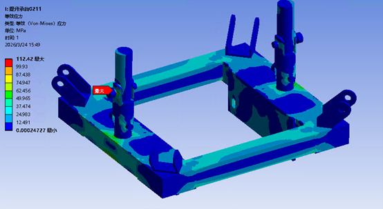
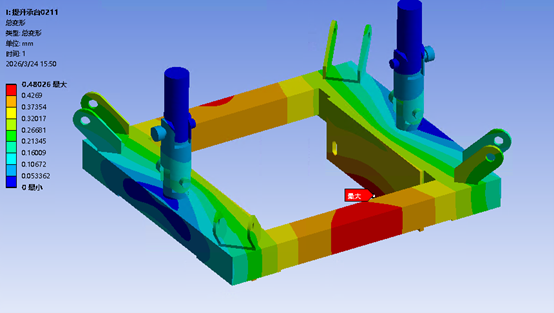
The key load-bearing structure is meshed, with lift loads, supports and connections applied. The platform and the frame are checked separately.
Lifting platform:
- von Mises peak 112.4 MPa, at the transition between the lug and the box beam;
- peak resultant displacement 0.48 mm, at mid-span of the box beam.
Frame:
- von Mises peak 19.3 MPa, mainly at column–brace joints;
- maximum displacement of about 0.35 mm under the same load case.
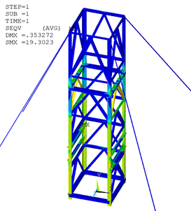
The results feed section and rib changes; they are not used only as a pass certificate. Platform stress is well above frame stress, so the lug transition is the first place to add a fillet or a stiffener; the frame still has a larger stress reserve.
4. Prototype and site assembly
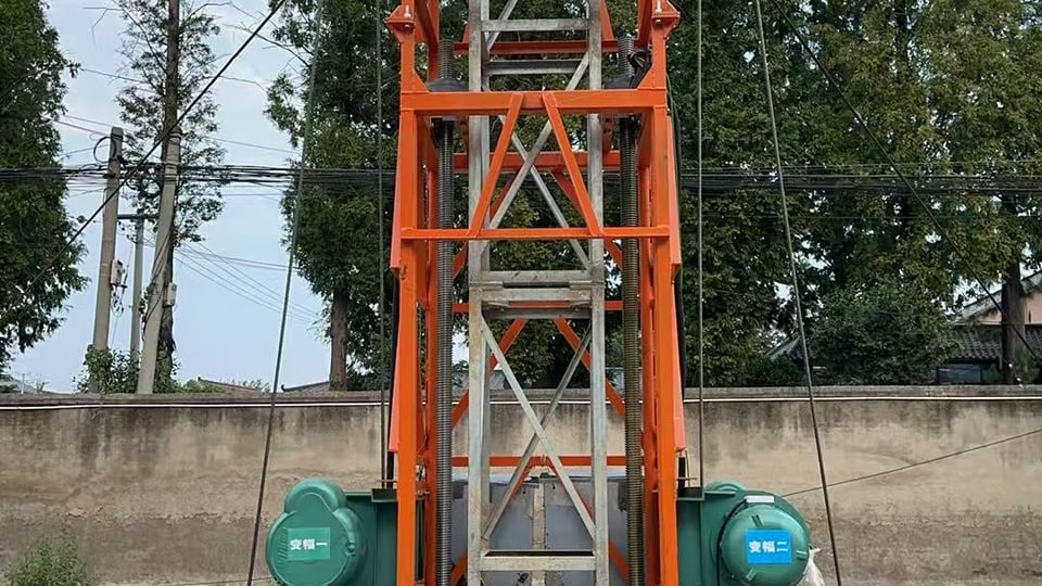
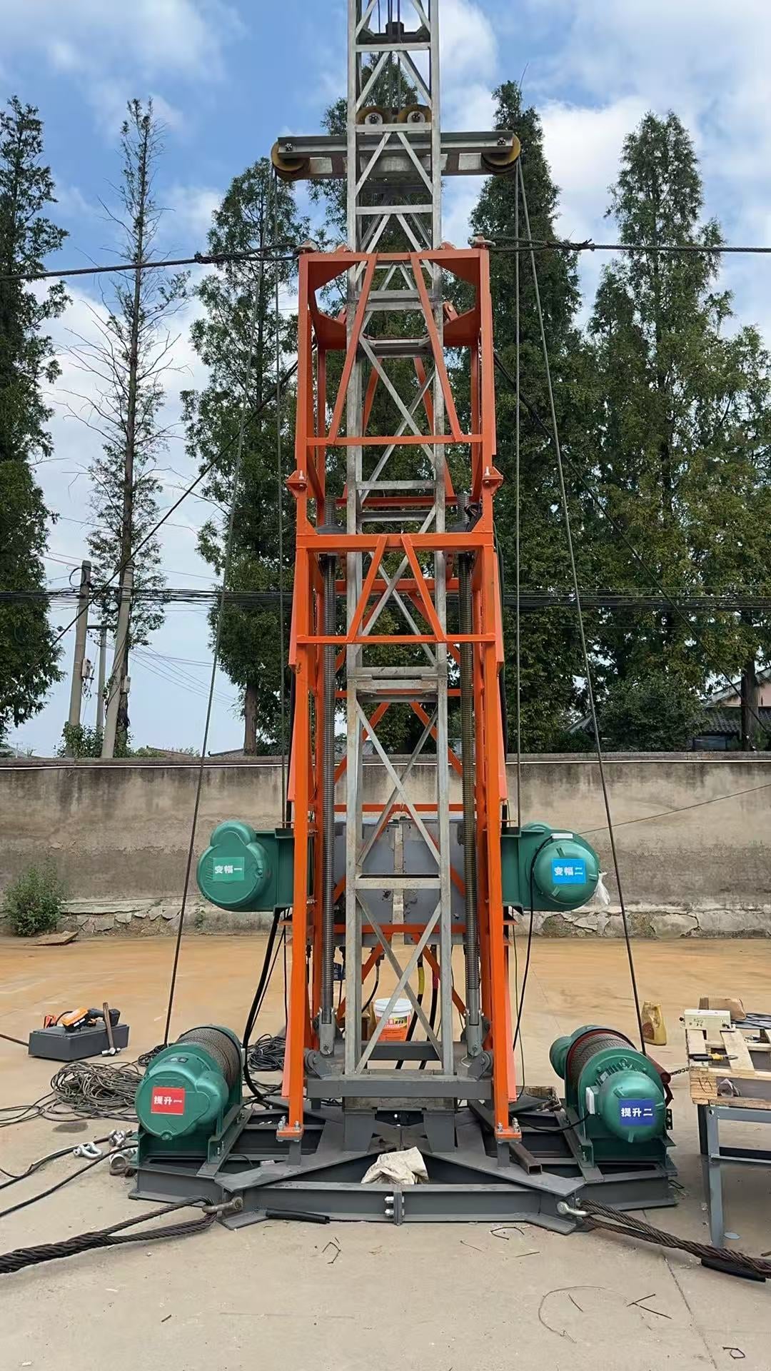
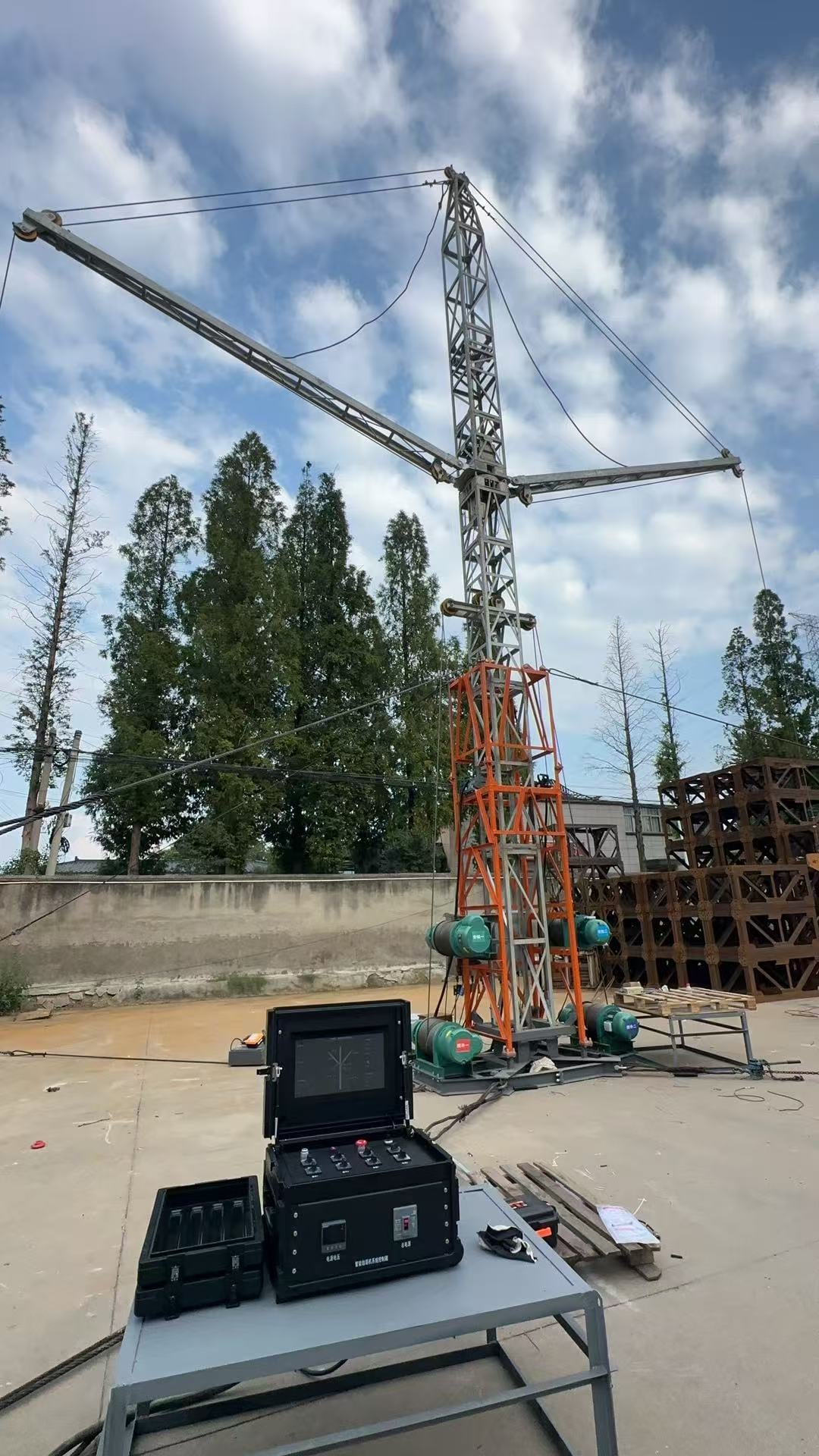
The scheme was fabricated. An orange lifting cage wraps the mast section, with vertical lead screws inside the cage; the side motors are labelled luffing 1 / 2, and the base winches hoisting 1 / 2. The full machine is assembled on site: double jibs, cage, base and a field control box.
The photographs show fabrication and assembly, not a load-test curve.
Role
Responsible for the mechanism change (rope to lead screw), motor sizing, platform and primary-member design, SolidWorks modelling, and ANSYS stress / displacement analysis of the load-bearing structure.
Evidence on this page
- SolidWorks assembly of the lead-screw, platform and frame columns
- Platform: von Mises peak 112.4 MPa, resultant displacement peak 0.48 mm
- Frame: von Mises peak 19.3 MPa, displacement about 0.35 mm
- Fabricated lifting cage with lead screws and motors
- Full machine on site: cage, double jibs and control box
Steel grade, allowable stress and factors of safety are not tabulated here. The contours are peaks for this load case, not a full load spectrum.
Skills
Mechanism design · Lightweight structures · Motor sizing · SolidWorks · ANSYS · Strength check · Stiffness check